Tianyi Sensor IOT Technology Co., Ltd
Sales Manager:Ms. Emily Wang
Cel,Whatsapp,Wechat:+86 15898932201
Email:info@fengtutec.com
Add:No. 155 Optoelectronic Industry Accelerator, Gaoxin District, Weifang, Shandong, China


Sales Manager:Ms. Emily Wang
Cel,Whatsapp,Wechat:+86 15898932201
Email:info@fengtutec.com
Add:No. 155 Optoelectronic Industry Accelerator, Gaoxin District, Weifang, Shandong, China
Model:FT-SJ20A
Brand:tianyi
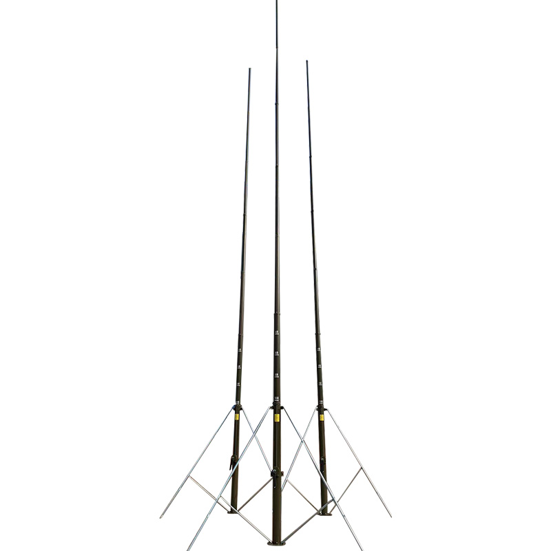
1.Manual adjustable lightning rod usage scope
The installation and support of various wireless communication antennas, lighting, cameras, night vision instruments, ordinary lightning rods and other equipment.Especially suitable for the installation and use of various instruments with strong mobility and frequent movement.Such as the installation and installation of satellite signal reception antennas and mobile radar lightning rods.
2.Manual adjustable lightning rod applicable environment
Working temperature: electric type -45℃~+55℃, manual type ±55℃.The maximum wind resistance is 30m/s (firm installation foundation and pull wire state), and the installation and use of various instruments that move frequently.Such as the installation and installation of satellite signal reception antennas and mobile radar lightning rods.Solid ground (indoor, outdoor), interior and exterior of vehicles, square warehouses, and installation of ships and offshore drilling platforms.
3.Manual adjustable lightning rod technical parameters
| Product Specifications | 10 meters | 12 meters | 15 meters | 20 meters | 30 meters |
| Expand height | 10003mm | 12000mm | 15007mm | 20000mm | 30000mm |
| Closed height | 2089mm | 2200mm | 2624mm | 2700mm | 3200mm |
| Rod body material | Magnesium alloy | Magnesium alloy | Magnesium alloy | Magnesium alloy | Four-button tube |
| Product weight | 40KG | 50KG | 60KG | 61KG | 120KG |
| Driver method | Manual | Manual | Manual | Manual | Manual |
| Wind resistance level | Level 8-10 | Level 8-10 | Level 8-10 | Level 8-10 | Level 8-10 |
| Rod body color | Military green | Military green | Military green | Military green | Military green |
| lightning rod | 0.5m special alloy lightning rod tip | Stainless steel lightning needle | 0.5m special alloy lightning rod tip | Stainless steel lightning needle | 0.5m special alloy lightning rod tip |
4.Manual adjustable lightning rod selection conditions
1.Determine the maximum lift, closing height, load bearing weight, and windward area of the carrier
2.Determine ground installation, exterior installation or interior installation
3.Determine whether to choose vertical or horizontal type of electric type
4.Electric type determines the use of power supply for the motor
5.Manual adjustable lightning rod structure characteristics and working principle
The structure is compact and consists of a lifting rod, a tripod bracket, a handcuff, a wire pulling system, etc.The power is transmitted by a combination of hand-crank shaft, bevel gear, lead screw, wire master and wire rope to achieve the purpose of lifting and lowering.The "extending mechanism" is used, that is, each section of the movable rod is lifted and lowered at the same time, with a fast speed, and the wire rope can be exposed after being raised.Can lock itself at any height position without sliding.
6.Manual adjustable lightning rod setup requirements
1.The lifting lightning rod must be installed on a flat and hard foundation to ensure that it does not sink or tilt after bearing load.
2.The loading of the lifting lightning rod is not allowed to exceed the specified weight.The loading must act on the axis of the rod body.Asymmetric loads that deviate from the axis are prohibited from causing the lifting lightning rod to tilt and bend.
3.The lifting lightning rod must be vertical to the horizontal plane, and the allowed inclination shall not exceed 0.5°.
4.When the wind speed exceeds 14m/S, there must be a pull wire for installation or lifting.
5.The closing lock hook must be removed before raising the lifting rod.
6.The fasteners with fixed load must be tightened before lifting.
7.It is strictly forbidden to hit and smash during use, installation or transportation to prevent the rod from deforming.
8.If abnormal phenomena such as inflexible lifting or stuck during the lifting process, you should stop working immediately, find out the cause and troubleshoot before operating.
9.Remember that the short pulling wire of the three-layer pulling box that pulls the fixed tube during the lifting and lowering process must be in the locking state, see Figure 1 for the locking state details.
7.Manual adjustable lightning rod ground setting, lifting and pulling wires
1.Choose a flat, hard and open site.The square and circle can meet the requirements of pulling wire nails, that is, the site is a circular area greater than or equal to R=12.6m.
2.Refer to Figure 2 to install the upper hinge, legs and oblique strut on the lifting rod and then install the pin.
3.Adjust the pull-line lock pins of the pull-line box to the unlocked state (that is, pull up the lock-line handle and rotate it 90° to make the lock-line handle boss escape from the lock body groove.
4.Hang the long, medium and short pull-line hooks of the pull-line box on the upper, middle and lower pull-line holes of the lifting rod respectively.
5.Install the load on the lift rod and tighten the fixing screws and remove the closing lock hook.
6.Stand up and hold the lifting rod, then expand the legs, pull out the telescopic rod lock and pull out the telescopic rod into place and lock it.
7.Place the foot pallet under the foot and rotate the adjustment bolt to fine-tune the foot so that all three legs are supported and make the lifting rod vertical.
8.Nail the three ground nails to the ground with the top of the normal lifting rod with the lifting rod as the center, and the radius of 12.6m, and the ground nail hanging ring is facing the lifting rod.
9.Hang the pull-box hooks of the three pull-boxes on the three floor nail hanging rings respectively.
10.Adjust the short pull-line lock pin of the pull-line box to make it in a locked state (that is, pull up the lock-line handle and rotate it by 90° so that the lock-line handle boss enters the lock body groove) Insert the pull-line box handle handle into the short pull-line box handle jack, rotate the pull-line box handle clockwise, shake the pull-line at three points at the same time, and fix the lifting rod in a vertical position.
11.Turn off the handshake cover, insert the handshake handle on the handshake, and shake the lift rod evenly clockwise.The handshake handle lift rod raise the lift rod.The pulling wire is raised while raising, and a special person is assigned to observe the verticality of the lifting rod.As needed, the pulling box operator is instructed to loosen or tighten the pulling wire to keep the lifting rod vertically.When you see a red marking line exposed at the lower part of the second section of the lower part or feel that it cannot shake, the lifting rod has risen to its maximum height.
12.Adjust the length of the wire box and the middle pull wire lock pin to make it in a locked state.Insert the pull wire box shaking handle into the length of the wire box and the middle pull wire shaker socket, rotate the pull wire box shaking handle clockwise and hear a clicking sound.Shake the pull wire tightly at three points at the same time, and fix the lifting rod in a vertical position.
8.Manual adjustable lightning rod lowering and dismantling
1.Shake the handle counterclockwise and slowly drop the lifting rod.The wire box operator follows the wire and follows
Observer directs to adjust the pull wire to keep the lift rod down vertically until the lift rod falls into place.
2.Hold the lifting rod, remove the pull-out box from the ground nail and then retract the leg telescopic rod inward.
3.Remove the legs and diagonal struts and lower the lift bar.
4.Remove the load, remove the pull-up hook, then hang the closing lock hook and tighten the closing lock, etc.
9.Manual adjustable lightning rod maintenance and maintenance
1.After the lifting rod is used in rain, it should be dried before falling down and then lowered to the closed state.
2.When the lifting rod is closed and placed in the open air, a protective cloth cover should be worn to prevent rain and dust from entering.
3.If not used for a long time, it will rise and dry every half month during the rainy season; if it rises and dry every one month during the non-rainy season.
4.After strong winds are made in the wild, check the installation of the lifting rod or every month.The rod body should not be tilted or deformed, and should not be loose.If problems are found, they should be eliminated in time.
What are the negative oxygen ion monitors? One is a detector suitable for scenic spots, and the other is a handheld negative ion detector.For the negative ion detector in scenic spots, the FT-FZ1 Scenic Air Negative Oxygen Ion Monitor can be selected. This monitor can monitor the concentration of ne...
Air quality monitoring stations for road traffic primarily aim to conduct real - time monitoring of air quality in traffic - intensive areas. They integrate data from environmental monitoring networks, meteorological parameters, and vehicle - related information. By doing so, these stations analyze...
Vehicle weather sensor integrates temperature, humidity, wind speed, wind direction, atmospheric pressure, and piezoelectric rainfall monitoring functions. It is a portable observation device designed for mobile platforms, capable of acquiring real-time meteorological data around the vehicle a...
In a tea plantation base, there is an Agricultural Weather Stations for the tea garden microclimate. Composed of devices such as cameras, digital displays, and smart agricultural monitoring sensors, it serves as the "smart brain" of the tea garden.The core, Agricultural Weather Stations, c...


 Get a Free Quote
 Skype
Skype
 whatsapp
 mail
mail